Single Digit - 0.31" (7.8mm) Seven Segment Display
Single Digit - 0.3″ (7.6mm) Seven Segment Display
Single Digit - 0.36″ (9.1mm) Seven Segment Display
4 x 4 2.0″ (50.1mm) Bi-Colour Dot Matrix Display
Single digit - 0.39″ (10mm) Seven Segment Display
Single Digit - 0.43″ (11mm) Seven Segment Display
Single Digit - 0.50″ (12.7mm) Seven Segment Display
Single Digit - 0.52″ (13.2mm) Seven Segment Display
Single Digit - 0.56″ (14.2mm) Seven Segment Display
Single Digit - 0.80″ (20mm) Seven Segment Display
Single Digit - 1.0″ (25mm) Seven Segment Display
Single Digit - 1.02″ (26mm) Seven Segment Display
Single Digit - 1.5″ (38.1mm) Seven Segment Display
Single Digit - 1.8″ (46mm) Seven Segment Display
Single Digit - 2.3″ (57mm) Seven Segment Display
Single Digit - 3.0″ (76mm) Seven Segment Display
Single Digit - 4.0″ (102mm) Seven Segment Display
4 x 4 4.2″ (108mm) Single Colour Dot Matrix Display
4 x 4 4.2″ (108mm) Bi-Colour Dot Matrix Display
4 x 4 2.0″ (50.1mm) Single Colour Dot Matrix Display
8 x 8 2.3″ (60mm) Bi-Colour Dot Matrix Display
8 x 8 1.9″ (48mm) Bi-Colour Dot Matrix Display
8 x 8 0.8″ (20mm) Bi-Colour Dot Matrix Display
8 x 8 1.3″ (32mm) White Dot Matrix Display
8 x 8 2.3″ (60mm) High Performance Dot Matrix Display
8 x 8 1.9″ (48mm) High Performance Dot Matrix Display
8 x 8 1.5″ (38mm) High Performance Dot Matrix Display
8 x 8 1.3″ (32mm) High Performance Dot Matrix Display
8 x 8 0.8″ (20mm) High Performance Dot Matrix Display
8 x 8 2.3″ (60mm) Single Colour Dot Matrix Display
8 x 8 1.9″ (48mm) Single Colour Dot Matrix Display
8 x 8 1.5″ (38mm) Single Colour Dot Matrix Display
8 x 8 1.3″ (32mm) Single Colour Dot Matrix Display
8 x 8 0.8″ (20mm) Single Colour Dot Matrix Display
5 x 8 4.8″ (121mm) Bi-Colour Dot Matrix Display
5 x 8 3.5″ (90mm) Bi-Colour Dot Matrix Display
5 x 8 2.4″ (61mm) Bi-Colour Dot Matrix Display
5 x 8 4.8″ (121mm) Single Colour Dot Matrix Display
5 x 8 3.5″ (90mm) Single Colour Dot Matrix Display
5 x 8 2.4″ (61mm) Single Colour Dot Matrix Display
5 x 8 1.5″ (38mm) Single Colour Dot Matrix Display
5 x 7 4.1″ (106mm) Bi-Colour Dot Matrix Display
5 x 7 3.1″ (80mm) Bi-Colour Dot Matrix Display
5 x 7 2.1″ (53mm) Bi-Colour Dot Matrix Display
5 x 7 1.2″ (30mm) Bi-Colour Dot Matrix Display
5 x 7 2.1″ (53mm) White Dot Matrix Display
5 x 7 1.2″ (30mm) White Dot Matrix Display
5 x 7 0.7″ (18mm) White Dot Matrix Display
5 x 7 2.1″ (53mm) High Performance Dot Matrix Display
5 x 7 1.2″ (30mm) High Performance Dot Matrix Display
5 x 7 0.7″ (18mm) High Performance Dot Matrix Display
5 x 7 4.1″ (106mm) Single Colour Dot Matrix Display
5 x 7 3.1″ (80mm) Single Colour Dot Matrix Display
5 x 7 1.2″ (30mm) Single Colour Dot Matrix Display
5 x 7 0.7″ (18mm) Single Colour Dot Matrix Display
1.8″ (46mm) Interlocking Seven Segment Display
1.5″ (38mm) Interlocking Seven Segment Display
1.0″ (25mm) Interlocking Seven Segment Display
0.8″ (20mm) Interlocking Seven Segment Display
0.56″ (14mm) Interlocking Seven Segment Display
0.56″ (14.2mm) Quad Digit Seven Segment Display
0.40″ (10.16mm) Quad Digit Seven Segment Display
0.39″ (10mm) Quad Digit Seven Segment Display
0.36″ (9.2mm) Quad Digit Seven Segment Display
0.56″ (14.2mm) Triple Digit Seven Segment Display
0.52″ (13.2mm) Triple Digit Seven Segment Display
0.4″ (10.2mm) Triple Digit Seven Segment Display
0.36″ (9.1mm) Triple Digit Seven Segment Display
0.8″ (20mm) Dual Digit Seven Segment Display
0.56″(14.2mm) Dual Digit Seven Segment Display
0.5″ (12.7mm) Dual Digit Seven Segment Display
0.4″ (10.2mm) Dual Digit Seven Segment Display
0.3″ (7.6mm) Dual Digit Seven Segment Display
0.56″ (14.2mm) White Seven Segment Display
0.39″ (10mm) White Seven Segment Display
0.3″ (7.6mm) White Seven Segment Display
8 x 8 1.3″ (32mm) Bi-Colour Dot Matrix Display
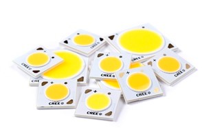
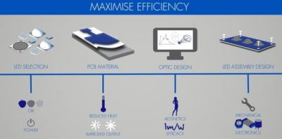
Chip-on-board (COB) LED arrays represent a cost-effective route to deliver performance, colour quality and reliability to an LED based lighting product.
As a designated Cree Solutions Provider, offering an integrated design and manufacturing service, Forge can help lighting OEMs to successfully apply both the ceramic-based CXA/CXB and the metal-based CMA/CMT chip-on-board LED technology; maximising the performance gains available from these exciting product platforms, including the latest XLamp® eTone™ LEDs - offing 90-CRI colour at the same efficacy at today's 80-CRI LEDs.
| High-Density Integrated Arrays | Small (<14mm LES) Standard- Density Integrated Arrays | Large (>14mm LES) Standard- Density Integrated Arrays |
|
|
|
Chip-on-board (COB) LED arrays have become an established and increasingly adopted method of applying LED technology in a diverse range of lighting applications.
Cree COB LED arrays comprise LED chips that are pre-mounted onto a thermally-efficient substrate and encapsulated beneath a layer of phosphor to create a light-emitting surface (LES). This packaging method, complete with on-board solder pads, makes COB LED arrays deceptively easy to assemble, however, in common with all other LED technology it is important not to overlook the consideration of a wide range of design principles necessary to achieve an efficient, reliable and truly cost effective lighting product, notably:
To help our customers all of these areas are considered as part of Forge’s service, and we actively welcome enquiries relating to how successfully integrate chip-on-board LED technology in demanding applications.
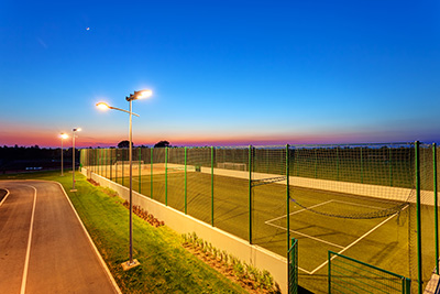
Outdoor amenity lighting is one of many applications where LED technology can deliver significant energy savings and a profound reduction in maintenance costs. The key to maximising these benefits in LED street lighting and wide area illumination products is the design of an LED assembly that incorporates the most efficient, highest efficacy LED possible, alongside a well-designed LED lens system to direct the light to where it is needed.
By selecting a high efficacy LED it is possible to achieve the high lumen output necessary for exterior illumination whilst using as little electrical power as possible. This reduction in power has an added benefit of maximising LED lifetime, as less power means less heat within the luminaire housing.
To achieve this high lumen per Watt figures it is important to take into consideration:
At Forge we routinely work with both aluminium and FR4 PCB materials; and for applications as demanding as street lighting we would recommend adopting the most thermally conductive material possible, which is aluminium IMS (isolated metal substrate).
Optical efficiency is fairly self-explanatory, if the lens is losing light as it works it towards the desired area for illumination then the practical lumens per Watt figure will reduce accordingly.
Colour rendering indicates how well a light source performs at representing colours. In certain applications is it is very important that a lamp achieves excellent colour rendition, for example in a retail environment, however for exterior area illumination the need to properly appreciate colours isn’t often a critical requirement. This is worthwhile considering because LEDs with high CRI values pay an efficiency penalty as they require the white light they emit to be comprised of a broader spectrum of colours. By having to work the blue light initially created within the LED into a wider range of wavelengths (colours) you effectively lose efficiency. So with exterior lighting it is favourable, and perfectly acceptable, to opt for a slightly lower CRI value to achieve better energy efficiency.
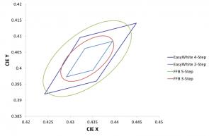
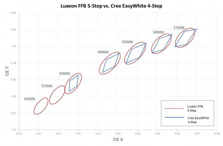
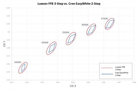
A question we are often asked here at Forge is how do the MacAdam-Step binning regimes of Cree and Lumileds compare? This brief article makes the comparison.
For reference:
The most striking difference, and indeed likely the source of a lot of the questions, is that Cree use a series of quadrants to define their EasyWhite™ colour bins whereas Lumileds use a set of ellipses as part of the ‘Freedom from Binning’ regime. Plotting quadrants is relatively straightforward using a spreadsheet application; however plotting ellipses and indeed rotated ellipses is a little more involved.
The outcome of plotting exercise is shown below for the various 3000K CCT bins.
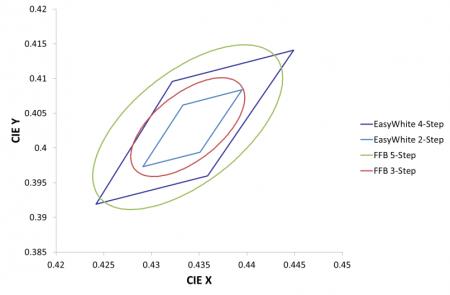
Which is best? Well it depends very much on your application and the cost constraints of the product. Narrower binning will always give better colour control and repeatability, but it will also involve an inevitable increase in cost.
Luxeon FFB-5 Step vs. Cree EasyWhite 4-Step
Luxeon FFB-3 Step vs. Cree Easywhite 2-Step
LED component manufacturers have revolutionised the lighting industry, offering energy efficiency, durability, and versatility for various applications. However, LED overheating remains a significant concern for manufacturers and users alike. Overheating leads to reduced LED performance, decreased lifespan, and in some cases, even safety hazards.
High-power lighting-class LEDs run at impressively high temperatures. But there’s a limit to how much power LEDs can handle, and it is essential that adequate heatsinking is provided to prevent overheating.
LED overheating has several causes, ranging from design flaws to environmental factors. One of the most common causes is poor LED thermal management, where the heat generated by the LED is not dissipated efficiently. This can happen due to inadequate heat sinks, insufficient ventilation, or using the wrong materials.
Another potential cause is electrical current issues, such as overdriving the LED, which can generate excess heat. Also, a well-designed LED luminaire can be overheated by installing in an environment for which it was not designed.
Ambient temperature plays a role in LED overheating, and high temperatures can cause LED components to fail. Other environmental factors, such as humidity and dust accumulation, can also contribute to overheating by reducing the effectiveness of heat sinks and ventilation.
Poor design and manufacturing processes can also lead to overheating, as defective components or faulty circuit designs can create excess heat or reduce the LED's ability to dissipate heat effectively. Overall, it is essential to identify the root cause of LED overheating, to implement the appropriate solutions and prevent future issues.
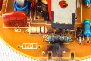
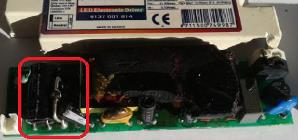
LED overheating can cause significant damage to both the LED and surrounding luminaire and create detrimental results.
The most significant impact overheating has on LEDs is to reduce their lifespan dramatically. Excessive heat causes thermal stress on the LED's components, such as the solder joints and circuit boards, leading to early failure. This results in costly repairs and replacements for end users.
Overheating may eventually cause damage to the surrounding luminaire, and excess heat can cause additional damage, such as warping and even cracking of the housing and other components. In addition, overheating can sometimes lead to fire hazards, particularly if the luminaire's electrical components are damaged or compromised.
Overheating can cause a significant change in LED colours, particularly for white LEDs. White LEDs are typically created using blue LED chips and a phosphor coating that converts blue light into white light. When overheating, the phosphor layer degrades, leading to a shift in the colour temperature of the LED.
This shift in colour temperature will have significant implications for the aesthetics of lighting applications, particularly those where consistent colour temperature is critical, such as in retail, museum settings or hospitality LED lighting. In some cases, overheating causes a significant change in LED colour, leading to a shift from white light to a different colour altogether. This is particularly damaging for applications where colour accuracy is essential, such as in photography, art installations or road safety lighting.
Lumen output (or lumen maintenance) is a term used to describe the gradual reduction of a light source's brightness over time. LED overheating significantly impacts lumen maintenance, gradually reducing the LED's overall brightness and efficiency.
When an LED overheats, it causes thermal stress on the LED's components, including the phosphor layer, which is responsible for converting blue LED light into white light. Over time, the phosphor layer breaks down due to high temperatures, significantly reducing lumen output.
Overheating may cause custom LED drivers and other electrical components to degrade, reducing the LED's overall efficiency and light output. This reduction in lumen output has significant negative implications for lighting applications, particularly in commercial LED lighting systems or industrial settings where consistent lighting levels are critical, resulting in increased maintenance
Here’s a list of general advice that will ensure the longevity of your LEDs:

At Forge, we have implemented many design strategies to prevent LED overheating, including well-designed LED thermal management.
Our expert engineers use advanced computer modelling and simulation tools to optimise the LED lighting systems they create for efficient heat dissipation, ensuring that heat generated by the LED is quickly and effectively removed.
We use the highest-quality materials for our heatsinks, such as aluminium, which has excellent thermal conductivity. This allows for effective heat transfer from the LED to the surrounding environment. By effectively managing heat through a great LED heatsink design, the LED will operate safely and efficiently, maintaining optimal performance and longevity. Contact us to discuss your application and discover how we ensure it resists overheating.
LED components can be designed and selected to offer reliability and long life. However it is also critical to consider the lifetime of the power supply unit, can this support and match the lifetime of the LED? Many LED users are unaware of the de-facto industry standard for driver failure: 0.2% per 1000 hours. So how do you build this into design considerations and product life expectations?
The three key factors affecting driver performance are:
Electronic products can be extremely reliable but ‘you get what you pay for’. In terms of value for money if you shift from price to performance and understand that the current industry rate is 0.2% per 1000 hours de-facto standard for lighting electronics, the quality of the electronic products you select and purchase has a direct impact on product life and LED performance. Always check manufacturer’s technical specifications for driver lifetime value and failure rates.
The lifetime of a driver is determined by the lifetime of its individual components. Factors affecting key component lifetime include:
Failure in any one can cause the lights to go out, flickering and EMC non-compliance etc.
Ineffective or faulty soldering can cause a driver/PSU to fail. Causes of poor soldering include low operator skill, poorly controlled manufacturing processes and quality assurance procedures. Again this can impact on a driver by causing the lights to go out. Prevention is pretty simple: control your manufacturing to the Electronic Industry’s ‘bible’ of soldering IPX-A-610-E!
Here’s a check list to help prevent driver/PSU failure:
Driverless LED light engines are PCBs that don't require the use of a power supply, ballast or control gear to enable them to operate successfully. For example, a driverless mains powered light engine can be connected directly to a 230V AC supply. For more information contact our sales team to find out more.
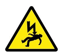
Rules and regulations covering electrical safety have been developed by the EU to prevent the hazard of electrical shock in varying installation and operating conditions. The mandated standards take into account changing levels of humidity, temperate and atmospheric conditions in order to set the minimum insulation distances required between exposed live parts and other user accessible areas.
Smaller than mandated insulation distances can directly present shock hazards, and also potential fire risks. If illegal product is installed into a publicly accessible location and a fire results, it could be the case that insurance is invalidated and first call liability falls with the owner/operator for installing and using products which contravene EU safety directives.
Electrostatic discharge (ESD) is a sudden transfer or ‘discharge’ of static charge from one object to another which can cause damage to LED components and assemblies. ESD is more commonly known as “static electricity”. The good news is that ESD damage is generally rare due to inbuilt LED protection, effective ESD handling and protection via circuitry. But the bad news is that it can be latent and cause reduced product life and eventual LED failure.
What causes ESD?
The first stage of an ESD event is the build-up of a static charge on an object, whether that is a surface, tool or indeed even a human! A static charge can exist on any object that has the properties of an electrical insulator and that is coming into contact with other materials. In other words, static charges are very common but often go unnoticed. An electrostatic discharge occurs when either an object comes into contact with an electrical conductor with a connection to ground or when two objects of opposing changes (negative and positive) come into contact.
What damage can ESD do?
The sudden movement of electrons that constitutes an ESD event can have a profound detrimental impact on electronic components. In the case of LEDs, ESD can result in the complete failure of a device, which results in the device not conducting current, a partial failure (such as a reduction in light output) or the creation of a latent defect that could manifest itself at a later date and shorten the lifetime of the LED.
How do I minimise ESD?
Prevention measures against ESD include: observing best practices in terms of ESD handling and designing in on-board in-circuit protection. ESD handling includes setting up and auditing activities within ESD protected areas that ensure safe handling of sensitive components as part of the manufacturing process, as ESD is most commonly caused by people!
In-circuit protection is often centred around the application of so-called transient-voltage suppressor (TVS) devices as part of the circuit design. These devices are designed not to conduct current until a certain threshold voltage is reached.
Stadium lighting, stage lighting, flashlights and retail spotlights; these are all applications that require high intensity light sources and that could benefit from the energy saving characteristics of LED technology.
The keys to achieving a high intensity light source are for the luminaire to possess all of the following characteristics:
Until now this is where LEDs have required the acceptance of a certain degree of compromise. Delivering a small apparent optical source meant limiting the overall area of the LED die at the heart of the device. This in turn limited the amount of light that could be generated within the package and resulted in a lower lumen output.
The following table outlines the typical performance differences between smaller die components such as the XP-E2, and larger die components, based on their use with an off-the-shelf 20mm diameter TIR optic. Note how the XP-E2 emits less than 25% of the lumens of an XP-L but delivers a maximum intensity (Cd) that is 28% higher than the more powerful component.
| XP-E2 | XP-G2 | XP-L | |
| Beam Angle | 8° | 11° | 17° |
| Cd/Im | 40.3 | 20.5 | 7.8 |
| Max Im | 309 Im | 590 Im | 1250 Im |
| Max Cd | 12,450 cd | 12,095 cd | 10.4W |
| Power @ Max Im | 3.3W | 4.9W | 10.4W |
| Cd/W | 3,772 | 2,468 | 937 |
As a result, Cree has gone back to the drawing board and developed a range of new High Intensity LED components, coupling small apparent optical sources with a highly efficient primary lens system that is designed to maximise light extraction.
The high intensity primary optic design is available as part of the XP-L High Intensity and XHP35 High Intensity components, with the planned addition of further new high intensity devices in the coming months.
So how can you maximise the benefits of this new technology? As a fully integrated LED solutions provider Forge can not only help you design and manufacture a high intensity LED light engine, but also go further and help you develop a custom LED optic to extract the maximum performance of the LED technology. We can tune the custom lens solution it to the exact photometric requirements of your application, whilst considering and wherever possible accommodating the mechanical and aesthetic demands of your finished lighting product.
For a few years now we’ve been reading various articles and studies regarding LED light for horticulture, horses and livestock. Where do we, the humble human being, fit into this scenario? Are we the forgotten species?
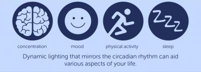
Circadian rhythms are mental and physical changes that naturally occur around a 24 hour cycle. These are the processes of living beings, plants, animals, fungi and, yes, humans! Circadian rhythms are important in determining behaviour patterns such as eating and sleeping, and can be influenced by external factors such as sunlight and temperature. This is where “human centric lighting” comes into play – the term for lighting which is designed to promote physical and mental health and even concentration and productivity.
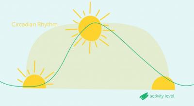
Daylight naturally increases the level of human activity whilst darkness readies the body for the sleep phase. With so many of us now spending our days cooped up in office buildings away from the natural sunlight that promotes our various physical and mental states throughout the day, dynamic lighting could have a real impact on mood and productivity.
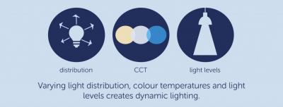
Dynamic lighting varies the lighting level, distribution and colour temperature, controlling the light to aid concentration, mood, physical activity and sleep. Bright light in the morning will improve mood and alertness, bright light in the evening can supress melatonin levels and affect sleep. With dynamic lighting evening light levels can be set at a much more comfortable colour temperature and brightness to allow melatonin production and aid a good night’s sleep.
Hospitals and care homes can benefit hugely from human centric lighting as residents, patients and staff have limited access to daylight. A light cycle that includes sunrise, daylight and sunset simulations can assist the natural circadian rhythm. This improves the patient’s mental wellness, preventing low moods and depression, encouraging communication and helping to induce sleep – reducing the need for antidepressants and sleeping aids.
The staff in a healthcare setting can also benefit. Not only is their wellbeing improved, they experience fewer headaches in the evening, and workload can be more effectively handled as patients experience activity and resting phases at the correct time.
Human centric lighting can not only replicate the usual light cycle to keep circadian rhythms aligned, it can also be used to shift the natural rhythm – for instances where shift workers are on a 4 or more night pattern shifting the rhythm to keep workers awake in the evening but allow for sleep straight after is advisable to improve productivity, alertness and even reduce accidents.
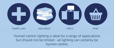
LEDs can play an important role in the delivery of human centric lighting, but the science must be right. Further knowledge and additional research is required in the area of human centric lighting to allow for successful implementation of such complex systems. With the required investment human centric lighting will certainly be a huge growth area in the next decade – and it should not be limited to industry, healthcare and education but to all lighting.

The LED Lighting industry has come a long way in the last 10 years. And the LEDs themselves have got better and better – or have they? One of the less well publicised and indeed less savoury aspects of lighting class LEDs is their ‘incompatibility’ with an increasingly wide range of chemicals.
If you’re not aware of this you should be!
Generally the problem is this – silicones, a family of materials used to form the primary lens or encapsulant of lighting class LEDs, can under conditions of energetic, short wavelength light and high temperature react with certain volatile organic compounds that are in close proximity to the LED. The end result is darkening of the silicone which typically results in a reduction in light emission and colour change.
Silicones are ideal in many respects for the production of LED components; as they can be engineered to exhibit certain properties that are advantageous both to the manufacture and in-service performance of LED components. Likewise, materials that contain volatile organic compounds, such as adhesives, sealants, solvents and conformal coatings, are fundamental to the realisation of the product. The presence of such materials may not even be known to you!
So what can be done? Well several things. Firstly, most major LED manufacturers compile white lists and black lists of known good/bad chemicals that have been tested with their products. But these lists are not exhaustive so the next line of defence is through thorough testing prior to volume manufacture. Thankfully most chemical incompatibility shows itself within a relatively short time period – days or weeks rather than months or years. So duly diligent trials will reveal any problems. But should problems still occur you will have to resort so some basic elimination-style forensic detective work to trace the cause.
The Forge Design Team enjoy an unrivalled perspective of up and coming LED developments and have noted a recent widening of availability of what can best be described as ‘niche’ LED colours.
In many cases these colours are previously unavailable in lighting class LEDs so whole new application areas can now be addressed. Many of these new colours are actually in new areas of the colour spectrum for LEDs – often way off the black body locus. And they have suitably exotic names such as ‘Purple-Pink’, ‘Yellow-Pink’, ‘Gold’, ‘Deep Gold’, ‘Violet’, ‘Pale Blue’, ‘Ice Blue’…
In our experience this kind of LED development is likely to find application in areas never before addressed but an obvious one is special purpose retail display lighting such as foodstuffs. Maybe ‘Pale blue’ for dairy products such as chilled cheeses, ‘Purple-Pink’ or ‘Yellow-Pink’ for red meats, ‘Violet’ for fresh fish, ‘Gold’ for breads – the only limit is your own imagination!
LED lighting is incredibly robust and reliable. However, the performance of LEDs can be reduced and even fail if the LED module is used incorrectly: overdriven or the application environment is too hot, and the unit has not been designed to be fit for purpose. Here’s an overview of the main causes of electrical overstress.
“Hot Connecting” means connecting a circuit comprising one or more bare LEDs to a LED Driver or LED Power Supply that is already powered-up or ‘live’.
Hot Connecting can result in a short but potentially harmful impulse of electrical energy being discharged from the live LED Driver or LED Power Supply into the LEDs. This in turn can result in either immediate damage to LEDs in terms of open-circuits or short-circuits, or latent damage that results in similar LED failure after a potentially long period of time (possibly up to many months).
This kind of LED damage is often categorised under the term Electrical Overstress (EOS).
High power LEDs that have suffered from failure due to Hot Connect EOS often show no naked-eye/visible signs of damage, but are frequently electrical short-circuits. Consequently they emit no light or only a very small amount of light and if they are connected in a series string the remaining/undamaged LEDs remain lit.
LEDs must be powered from a DC source that limits the current flowing through them. This is in contrast to incandescent lamps that will operate from AC or DC and which generally require no separate current limiting, or fluorescent lamps that operate from AC only but which do require current limiting (i.e. ballast or control gear).
If LEDs are connected directly to the UK 230V AC mains supply without any current limiting LED Driver or LED Power Supply they will most likely immediately and catastrophically fail open-circuit, possibly breaking apart explosively in the process.
If LEDs are powered via a LED Driver or LED Power Supply that supplies incorrect current and/or incorrect voltage several outcomes are possible. If the current and/or voltage is too low the LEDs will appear too dim, or fail to light at all. If the current and/or voltage is too high the LEDs could either age prematurely (in the case of minor overdrive) or fail catastrophically (in the case of major overdrive) with all scenarios in between being possible.
LEDs that have failed catastrophically due to direct mains connection will typically exhibit severe physical damage including breakage and burn marks. However, damage resulting from incorrect drive current and/or voltage may be manifest in many ways ranging from dimly lit but normal-looking LEDs through to severe physical damage.
LEDs do not emit the same amount of light of the same colour eternally! The amount of light reduces exponentially and the colour of white LEDs tends to become bluer – both as a function of time and temperature. The hotter the environment the shorter the LED life.
LEDs installed in an environment that is too hot will emit less light than intended and degrade more rapidly than intended both in terms of reduced light output and colour change. In extreme cases, physical damage can occur.
Minor LED overheat that results in premature light output/colour degradation may have no physical signs other than the reduction in brightness and colour change. Major overheat, however, can result in visible off-state discolouration and physical heat damage to the LED and surrounding components.
LEDs are electrically polarised and will only operate correctly when their positive terminal (also known as the anode) is connected to the supply positive and their negative terminal (also known as the cathode) is connected to the supply negative. LED connection polarity must be strictly observed!
If LEDs are reverse-connected to a sufficiently low voltage supply it is possible that they will simply conduct no current, emit no light and suffer no damage. In such cases correcting the polarity will result in correct LED operation with no adverse effects. However, if the supply voltage is sufficiently high then immediate and catastrophic damage can be caused resulting in no light emission and typically open-circuit failure.
Incorrect polarity connection that has caused LED failure will typically result in no light emission and open-circuit LEDs. This could result in signatures ranging from no naked-eye/visible signs of damage to physical damage including signs of burn/overheat.
We always consider effective thermal management, optical and electrical design, and can talk through options on adding protection circuits to protect against incorrect use or “hot-plugging”.

David Scott-Maxwell, our Managing Director, discusses the merits of LED light source standards.
The world of LED lighting continues to develop and expand at an incredible pace. And like a boat struggling to hold its anchor against a flood tide a brave group of businesses is trying to establish ‘standards’ that allow lighting manufacturers & end users to interchange light sources. This is of course the Zhaga consortium. Formed in 2010 and now boasting 146 member companies, it is attempting to ‘standardise where no one has standardised before’. But will these standards endure and be with us in 20 years’ time, or will they be swept away by the pace of LED technology?
In order to understand the motivation for LED ‘standardisation’ it is helpful to review the history of lighting. Lighting technology has until very recently grown incredibly slowly. Arguably there have been only three turning points: Gas Lighting in the early 1800’s, Electric Filament in the late 1800’s and Fluorescent in the early 1900’s. Each development has had decades to mature and consequently standards have grown slowly and organically. For example the Edison Screw lamp was first launched in the early 1900’s and is still in use today, over a hundred years later! But the ‘standard’ for lamp types IEC60061 was only published in 1970 ie it took 60 years to develop. With the pace of lighting technology development historically spanning generations the LED ‘revolution’ of the last decade has rewritten the rule book. New LED components of every shape, size, efficiency, cost, colour etc continue to be invented and not a month goes by without exciting developments. So the LED revolution has a long way to go and there is no sign of the rate of LED development letting up. With this background its’ easy to see why the traditional ‘Lighting industry’ would want to establish standards. It’s the only way to ensure a harmonised supply chain which is what the lighting industry has been based on within living memory.
So to this end the efforts of the Zhaga consortium are to be applauded. But in my opinion they are misplaced and they will ultimately fail. Why? Because LED lighting technology is really still in its infancy, so standards established now stand to be obsolete almost before they are published. And more subtly but just as importantly standards restrict creative freedom. And creative freedom in lighting is surely the single greatest asset of LEDs as light sources.
There are many technical terms that cover the measurements and characteristics of light. Here’s a selection of the essential terms.
Beam Angle / Viewing Angle / FWHM
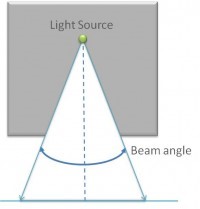
The LED beam angle, or LED viewing angle as it is also commonly referred, measures the usable light emitted from an LED source.
In most common situations, one of two methods is used to define the beam angle; the first looks for the angle at which 50% of the peak intensity is reached on either side of the origin. The second looks for the angle at which 10% of the peak intensity is reached on each side of the origin. Most commonly used is the Full Width, Half Maximum (FWHM) relating to 50% intensity, if for example an LED was measured to have 50% intensity at 15° it’s viewing angle (FWHM) would be 30°.
Luminous Flux (ΦV) – Lumens
Total amount of visible light emitted by a lamp. This corresponds to the total radiant flux of a lamp adjusted for the human eyes photopicsensitivity.
Luminous Intensity (IV) – Candela (or millicandela)
Luminous flux emitted per solid angle in a specified direction. Intensity is measured in units of lumens per steradian (lm/sr) or candela (Cd).
Illuminance (EV) – Lux
Illuminance is the luminous flux received at a surface per unit area. Illuminance varies with distance (inverse squared rule) and angle of illumination (Lamberts cosine rule). Illuminance is measured in units of lumens per square meter (lm/m2) or lux (lx).
Luminance (LV) – Nits
Luminance is the luminous flux emitted per solid angle per unit area – often referred to as brightness. Luminance is measured in the units of lumens per steradian per square meter (lm/sr.m2) or candela per square meter (Cd/m2), also known as nits.
Solid Angle (Ω)
A solid angle is the surface area of a sphere corresponding a specific beam angle. The unit of solid angle is the steradian.
Where, α = the full width angle in degrees
EMC, EMI and the importance of Electrical Safety
Electromagnetic Compatibility (EMC)
Electromagnetic Compatibility (EMC) has two fundamental goals:
The aim of EMC standards are not to achieve or guarantee absolute protection, e.g. zero emissions and total immunity. Attaining such performance would likely entail significant cost and impact upon the physical size and practicality of the end-product.
Electromagnetic Interference (EMI)
Electromagnetic interference (EMI) is defined as being disturbance that affects an electrical circuit via either electromagnetic induction or electromagnetic radiation emitted from an external source. The source may be any object, artificial or natural, that carries rapidly changing electrical currents, such as an electrical circuit, the Sun or the Northern Lights.
EMI has effects ranging from degradation of data through to total data loss in some electrical systems. Equipment that can be affected includes:
This list is not exhaustive.
Electrical Safety
Rules and regulations surrounding electrical safety have been developed by the EU to prevent the hazard of electrical shock in varying installation and operating conditions, the mandated standards take into account changing levels of humidity, temperate and atmospheric conditions in order to set the min required insulation distances between exposed live parts and other user accessible areas.
Smaller than mandated insulation distances can directly present shock hazards, but are also potential fire risks. If illegal product is installed into a publically accessible location and a fire results, it could be the case that insurance is invalidated and first call liability falls with the owner / operator for installing and using products which contravene EU safety directives.
The LED lighting industry is awash with confusing jargon and abbreviations. Here’s four for starters:- L70, LM79, LM80, TM21. So what do they mean?
L70 is simply a measure of the time taken for a light source to degrade to 70% of its original output. It is usually measured in hours and usually refers to degradation of total light output ie lumens. As in “my new LED L70 is 123hours” (not a good result, must try harder).
LM79, more properly referred to as “LM-79-08” is a Test Method authored by the Illuminating Engineering Society of North America (IESNA) titled “Approved Method: Electrical and Photometric Measurements of Solid-State Lighting Products”. This essentially defines a set of methodologies for laboratory testing of solid state luminaires and other light sources.
LM80, more properly referred to as “LM-80-08” is also a Test Method authored by the IESNA. It is titled “Approved Method: Measuring Lumen Maintenance of LED Light Sources”. In contrast to LM79 this defines a test method for long-term life testing of component-level LED devices.
LM80 is not much use on its own and does not of itself define how to extrapolate lab-measured LED lifetime test data to enable future lifetime prediction. That’s where TM21 comes in. Full name “TM-21-11”, titled “Projecting Long Term Lumen Maintenance of LED Light Sources”, TM21 details how to extrapolate short-term LED component test data to predict future performance.
Outdoor amenity lighting is the perfect application to benefit from LED technology. From reducing maintenance costs and saving energy to reducing light losses and power consumption, LED is the ideal solution.
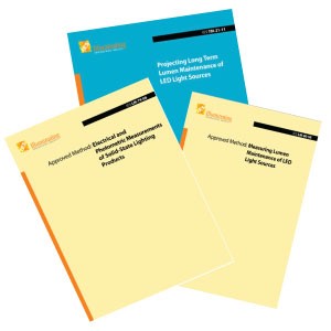
When designing your amenity lighting product – be it a car park light, floodlight, pathway light or any wide area illumination product – there are 4 factors to consider to achieve an outstanding solution.
First things first, LED device selection is critical to achieve the high lumen output necessary for exterior illumination. Colour Rendering Index (CRI) must be a consideration at this stage. CRI is the indicator for how well a light source performs at representing colours. In certain applications it is very important that a lamp achieves excellent colour rendition, particularly within the retail sector. CRI is often not so critical for exterior area illumination, so it is perfectly acceptable to opt for slightly lower CRI values. This allows you to achieve greater energy efficiency as higher CRILEDs lose efficiency due to working the blue light, initially created, within the LED into a wider range of wavelengths.
In order to achieve the high lumen output necessary for exterior illumination LED device selection also must review: high efficacy, high lumen density and high intensity LEDs, to get the best possible performance and light output. By selecting a high efficacy LED it is possible to achieve a high lumen output whilst using as little electrical power as possible. This reduction in power has an added benefit of maximising LED lifetime, as less power means less heat within the luminaire housing, not to mention the positive effect on the UMSUG rating.
Heat can be reduced further when selecting a suitable PCB material. Exterior lighting products can be very demanding and heat build-up could, not only reduce light-out, but impact on the overall product life. Highly thermally conductive materials need to be evaluated, with aluminium IMS (isolated metal substrate) being a possible solution.
If the lens is losing light then the practical lumens per Watt figure will reduce accordingly, therefore optical efficiency needs to be thought about to avoid any unnecessary light losses and put all the emitted light exactly where you need it. In addition to efficiency a custom optic design can enhance aesthetic appeal and help generate unique features.
Once the LED has been selected, the optimum PCB chosen and the optic considered the design of the complete LED assembly is critical. This is the final piece of the puzzle which considers factors such as; heat sink interface, the incorporation of microwave sensors, wiring restrictions and mechanical constraints resulting in the best possible assembly that has been cost engineered and doesn’t impact on performance.
To further maximise efficiencies a completely customised solution, designed and manufactured by us, will allow for full integration with your existing housing. You can then also have a fully branded solution that is just for you – not only will it put light where you need it most but it will put you way ahead of the competition.
If you have followed the development of lighting-class LEDs over the last 10 years you will have undoubtedly witnessed an output race unfolding between the leading LED manufacturers. This competition has yielded ever increasing performance from higher power components that emit more light from a single package.
In parallel to the improvements in higher power LEDs there has also been significant innovation in the field of mid-power LED components.
Initially the advancements were focused on creating improved backlights, principally to serve the market for flat screen TVs, however, the development effort ultimately yielded mid-power LED technology that attained the performance, reliability and unit cost, thanks to benefiting for significant economies of scale, to be considered for use in lighting applications.
So when should you consider mid-power LEDs? Non-directional lighting applications, particularly those demanding a homogenous light output over a large illuminated area, are ideally suited to mid-power components. Such applications highlight the flexibility of being able to place relatively low-cost components over a large area, dispersing not only light sources but also heat sources, and in doing so enabling better thermal management of the LEDs and the delivery of a more optimal design for the LED light engine. It’s important though to consider that every application should be treated on its merits, as there is no one-size-fits-all approach to cater for every nuance of a lighting application.
If you’re a lighting manufacturer looking to consider a mid-power LED light source for your latest product development, please feel free to contact our technical sales team who will be more than happy to discuss how Forge can help you realise the potential of the latest technology.
There’s a lot of talk about ‘Photo-Biological Safety’ in the LED lighting world these days. Mainly because on 27 April 2010 the ‘Control of Artificial Optical Radiation at Work Regulations’ came into effect in UK law, enforcing light exposure limits in the workplace.
So what’s it all about? A little Googling leads one fairly readily to an international standard:
BS EN 62471:2008 Photo biological safety of lamps and lamp systems.
For a mere £182 you can own a copy! Unfortunately, however, this is where for many folk it all starts getting horribly complicated. For this is no bedtime read. It is 52 dense pages of physics, mathematics & biology – more like a PhD thesis than an International Standard!
So this overview aims to unravel some of the mystery of Photo-Biological Safety and its guardian standard, BS EN 62471. It must be noted that this standard is also referenced in the EU Low Voltage Directive so must be considered when assessing products for electrical safety (products outside the LVD could be included via the General Product Safety Directive).
Let’s start at the end and look at the output of the standard. This is fairly simple – categorisation of lamps and luminaires into ‘Risk Groups’ with associated ‘Exposure Limits’. There are 4 Risk Groups defined:
The ‘Risk’ referred to is subdivided into the risk of physical harm arising from exposure to 8 different categories of light ranging from the Ultra Violet to the Infra-Red, each with associated maximum exposure times. It is important to note that BS EN 62471 only defines these risk groups – it does not mandate any product labelling or such as is done eg by the Laser Safety standards. So the standard is really only a metric for photo biological risk, rather than a control.
That’s the easy bit. The challenge for the luminaire manufacturer is figuring out how to assess which Risk Group a lamp or luminaire is in – i.e. how to interpret and use the standard. To cut a long story short, the answer is by means of a large number of optical measurements and a lot of mathematics! In practice, it’s necessary to make full spectral photometric measurements of a sample lamp/luminaire. Processing the measurement data can then be performed mechanically e.g. by spreadsheet or commercially available software.
In summary then, light sources that come under the Low Voltage Directive need to be assessed for photo biological safety – but no action is specifically required by the referenced standard. And all luminaire and lamp manufacturers need to be aware of the implications of the Artificial Optical Radiation Directive as do employers in general.
Colour rending metrics assign a rating to light sources using pre-defined test colour samples, these metrics are designed to compare a sources’ ability to accurately render colour.
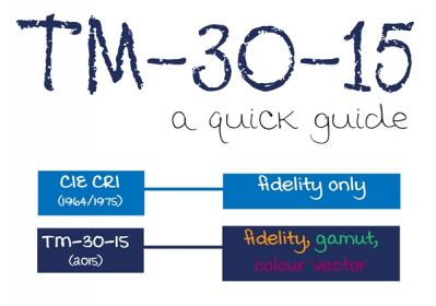
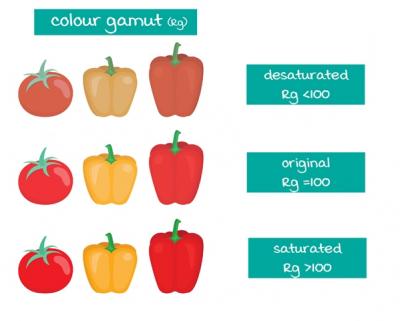
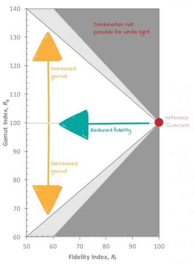
TM-30-15 is a new method to evaluate colour rendition; it includes several measures and graphics to evaluate the Fidelity (Rf) and Gamut (Rg) of a source when compared to a reference illuminant – a tungsten halogen. Unlike the Colour Rendering Index (CRI) which only considers the average accuracy of limited colour samples, TM-30 widens the comparative colour samples and offers a more comprehensive way to evaluate overall rendition.
The Fidelity index (Rf) of TM-30 uses the average value of 99 colour samples; CRI however, only uses 8 to generate the Ra value – why does this matter? Well, there are many more than 8 colours within the visible spectrum, so using such a limited sample set to try and describe colour rendering performance means that the reproduction of a subject’s visual appearance may vary significantly under the artificial source when compared to natural daylight. An Rf value of 100 means that the test sources renders the colour samples in exactly the same way as the reference source and therefore is very close to natural daylight.
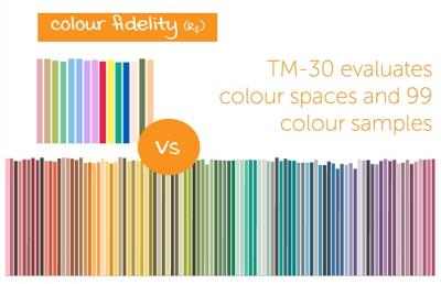
The colour Gamut index (Rg), represents the average saturation shift of the source compared to the reference illuminant. Values greater than 100 can be visualised as an increase in average saturation, whereas values less than 100 represent a decrease.
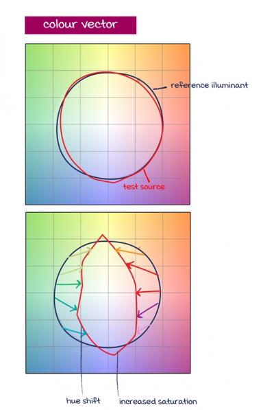
In addition to the two indices, Colour Vector Graphics are used to visually highlight gamut changes. The reference illuminant is represented by the black circle; deviation outside of this region shows an increase in saturation for the given colour, whereas a shift within, shows saturation decrease for the given hue. The accompanying arrows between reference and source depict the gamut vector shift.
We have a wealth of experience in a variety of industries – retail, hospitality, office lighting and leisure lighting to name but a few. More and more we find customers specifying LEDs with higher Ra as colour quality and rendering grows in importance. In a retail environment eye appeal is buy appeal so making shoes as vibrant as possible is a great sales technique and something clever lighting can assist with. However, fidelity by itself (which is what CIE CRI only considers) is not a complete measure to truly define a light source. It is possible for 2 light sources to have the same Ra value yet the visual perception can be completely different.
Simply specifying a high CRI LED may not give you the desired effect. As TM-30 brings in additional information designing and specifying becomes much easier and more controlled. TM-30 quantifies colour fidelity across 99 colour samples (CIE only uses 8), the higher the score (0-100) the more accurately the colours will render compared to the reference illuminant. It then introduces the Gamut index (Rf). 2 light sources with the same Rf value may differ just as those with the same Ra value might. One may well enhance the red whilst another mutes it – there will be a visual difference. The addition of gamut more accurately predicts how objects and spaces will look by measuring the average shift in saturation and hue. Lighting design is all about how the space will look so the greater control you can have of this the better. Whilst TM-30 is not yet a standard it certainly is a useful method that overcomes many shortcomings of CIE CRI.
So where does this leave you? As mentioned TM-30 is not yet a standard but, as more and more customers come to us discussing their very specific colour rendering needs, we have aligned our light characterisation reports to include TM-30 testing. We’ll do all the calculations and the hard work and you can benefit from the getting exactly what you want – it’s all part of the service.
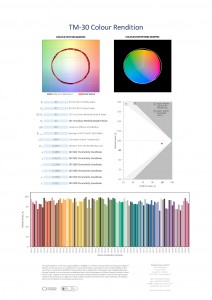
The addition has allowed customers creating a lighting scheme needing high fidelity and an enhanced saturation of specific colours, such as red, to do just that, for a high end retail display application.
Forge designed and manufactured a custom 2700K flexible LED product which allowed for a very simple yet visually stunning and effective solution ideal for retail with an Rf value of 95 and 106 Rg. If colour rendering and quality is of importance to you and your application then you need to speak to Forge today. We have a fantastic team, including industry specialists and technical gurus, ready to understand your needs and design and manufacture a solution just for you – the TM-30 testing is just one of the many additional benefits you can enjoy. Check out example test reports below.
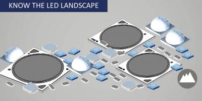
You are spoilt for choice in the marketplace for LEDs with multiple package offerings from numerous manufacturers. Knowing what LED components are out there is key to you knowing what works best within your application. We are consistently overloaded with the latest LED developments and simply chasing these will not result in a suitable LED that is optimal for your specification – don’t overlook your end-use application for the sake of being flashy. Knowing the LED landscape, whilst remembering your own requirements, is fundamental to selecting the best component for you.
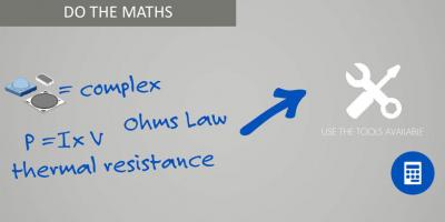
Remember those school day maths classes that we all undoubtedly paid grave attention to? Just as well, as LEDs are not simple; they are in fact highly complex compound semiconductors – without doing at least basic maths you will get it wrong. There is an array of online tools from many leading manufacturers. Use these tools as a starting point for basic modelling of the performance of the LED devices.
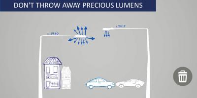
You’ve worked hard selecting the very best LED device for your application so now you must remember to direct the light to only where it needs to be and optimise the light fixture by considering materials, reflectors and optics. Use all the light you’re paying for and don’t go throwing away those precious lumens.
The LED industry has begun to get its house in order when it comes to LED lifetime evaluation, which is a fantastic achievement. Spurious lifetime claims have the potential to cause the wider lighting market to lose confidence in the reliability and legitimacy of LED technology. Make use of the LM-80 data that is available; indeed shout from the rooftops that your product uses LEDs that are backed up by industry-standard testing methodologies!
A custom LED optic enables your product to make better, more efficient use of the light output from LEDs and what’s more it’s not as difficult or as expensive as you might think. You could always use a standard off-the-shelf optic with your cleverly designed custom PCB: but with a little effort and a small upfront investment, you’ll have the perfect accessory to improve your solution and its overall aesthetic appeal.
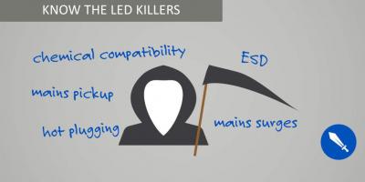
There are a number of potential LED killers that you need to be aware of:
Remembering these could just help you avoid catastrophic failure or latent defects within the LED components. After all, you’ve just spent considerable time and money perfecting your LED solution so don’t undo all that good work and compromise the longevity of your overall system.
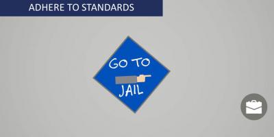
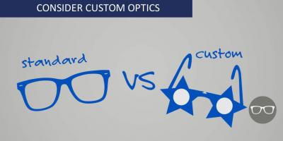
Don’t go thinking that because LEDs are relatively new to the lighting space you can avoid standards. Your lighting products must conform to the same safety standards as other light sources – this is not an optional extra, it is a requirement.
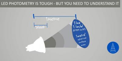
By now we have established that LED components are not simple and emit light in ways that are novel to those of the more traditional lighting technologies. LEDs are point sources of light that are omnidirectional not only that but there are colour uniformity and emission spectra to consider. You will need to understand LED photometry otherwise you’ll fail to understand LEDs themselves. You can join a trade association or use laboratories either way you need to get trained.
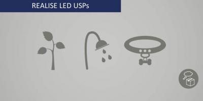
There’s probably an LED for almost anything – if you can think of it you’ll probably find an LED for it. Whether you’re illuminating dog collars, customising trainers or growing plants applying LED technology could just be the innovation you were waiting for. New markets are opening all the time thanks to ingenious and fresh ideas that don’t overlook the potential of LED.
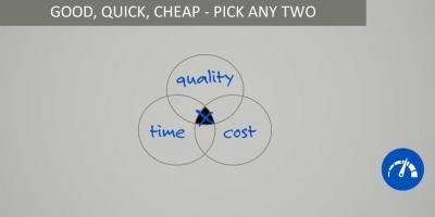
LEDs are not immune to the usual constraints of project management. When you are developing your custom LED lighting solution remember that you can have a low-quality product quickly but it will cost you, and a high-quality low-cost solution will take some time. Know what you want from the outset and you won’t go far wrong.
High lumen density LEDs are one of the latest technology developments to emerge aimed at reducing LED lighting system costs. In many cases the LED no longer constitutes the largest cost element of an overall system; however the characteristics of an LED can often be the determining factor in the performance and total system cost of an LED lighting product.
Lighting OEMs can significantly reduce system size and system cost by using fewer, more-robust and reliable high lumen density LED components to achieve the same overall flux, intensity and life as larger, and more complex LED solutions.
The following are our top tips for using high lumen density LEDs:
High lumen density LEDs enable the creation of small, super-bright luminaires that can save you some serious cash on materials. To realise their full potential it is of critical importance that you keep super close eye on the thermal design of the luminaire. Of particular significance are the solder joints, PCB material, thermal interface materials and heat sink which form the key elements of the thermal path between the LED and the ambient environment.
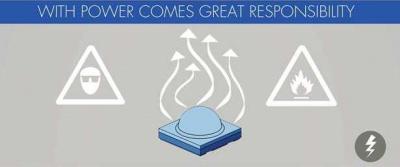
The photometric power of high lumen density LEDs is colossal. You must always follow eye safety recommendations and use appropriate protection when working with bare LEDs during product development. You need to be particularly wary of fire risk caused by the photometric power near to the LED emitter, dark coloured materials are dark for a reason; they are absorbing a huge fraction of the light – and therefore energy – coming from the LED!
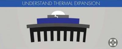
The latest generation of LEDs can be operated at higher temperatures and still maintain an adequate lifetime, this is especially true for the cutting-edge high lumen density LEDs. Under these conditions it is important you evaluate the thermal expansion coefficients (CTE) of elements such as; the solder and PCB materials used within the end product, as mismatched CTE’s can lead to premature failure of the LED system.
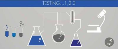
So, you have experience working with LED components? Don’t start thinking that means you can avoid testing. The revolutionary nature of high lumen density LEDs means that in addition to outstanding performance you also get to tackle some new challenges. For example, the increased radiated power of high lumen density LED components means that you will most likely need to revisit chemical compatibility, as increased radiated energy creates a more aggressive environment that can bring about unwanted chemical changes.
Download our light engine brochure now.
Download our flexible LED brochure now
Got chills!? Check out the solutions we have that are ideal for refrigeration applications.
Our custom optical design service ensures peak performance for any LED.
The LED has changed many ways of doing things, but none so much as the ability to shape light. From the basic light bulb to the most sophisticated roadway lighting, every light source involves some kind of control methodology to deliver the desired light pattern. And, by sheer necessity, LED technology has required an entirely new development in light science: the miniature lens.
Traditionally, we wrapped a reflector system around a lamp to provide the primary beam control – a primary control that, for the most part, meant that all the available light went forwards rather than anywhere else. Theatre and some architectural fixtures employed a secondary lens arrangement to provide further light control, opening or closing the beam, hardening and softening the focus. But the form factor of the LED has changed all of that.
Unlike previous light sources, LEDs are not omnidirectional. Mounted on a substrate, the light from the chip or module is necessarily directed outwards, somewhere within a hemispherical cone of light. This calls for a different approach to control. If we add the physical issue of the LED being such a tiny light source, we can see why new optical technology has developed.
Early LED modules tried to make do with optical control mounted within the LED chip or module, but it became clear from the huge variety of demands on the use of a chip or module that on-board optical control either restricted light-in-use options, or was simply too expensive to produce. Which brings us to the purpose of this piece – the rise of the custom optic.
We offer a custom LED optical design and manufacturing service. Using bespoke toolsets, optics can be designed for LEDs from any manufacturer for any purpose. Mechanical and photometric design is developed using the latest CAD software, including visualisation tools capable of rendering graphics of the planned light performances within the spatial environment.
In producing our custom LED optics, we aim to typically achieve >90% transmission through the lens. The selection of the optic material depends on the demands of the project.
Polycarbonate has a high refractive index and is a good material to employ when there are space restrictions. It’s a softer material and prone to scratching. And, as we all know, it has good impact resistance.
There is also the option of adding an anti-reflective coating. This can increase transmission values by >4% and help provide a more scratch-resistant surface.
PMMA (polymethyl methacrylate) offers better transmission and is hard-wearing and scratch-resistant. It’s also an excellent material when working with larger lenses. However, it’s best suited to a low operating temperature, which can limit its usage.
Glass (and borosilicate glass) offers excellent transmission and is hard-wearing with good strength. Glass is not suitable for injection moulding and small details are difficult or impossible to achieve. It can handle thermal shocks well, provided that expansion and contraction have been allowed for in the luminaire design.
Silicone has a lower refractive index, but can incorporate undercuts due to the material’s flexibility when being removed from the mould. It can ‘bend’ light well and is stable at high temperatures.
We manufacture custom optics for all types of lighting application, from single optic lenses for architectural and task lighting to multi-array lenses for street lighting and industrial applications.
Using bespoke toolsets, optics can be designed for LEDs from any manufacturer for any purpose. View our video now to find out more.
Download our displays brochure now.
Download info on our custom Iced Pro
Tunable white LED solutions are the easiest and most cost-effective way to take control of your lighting. A tunable solution allows your product to tune between 2 colour temperatures creating cracking mood lighting, simulating daylight or simply enhancing your lighting scheme. With good lighting now an expectation integrating tunable technology into your lighting, with the help of Forge, is one of the simplest ways to get good lighting.

Tunable LED solutions are perfect for healthcare and workplace applications improving health, productivity and safety in educational and medical scenarios. Mixing between 2 colour temperatures allows for daylight to be mimicked and circadian rhythms to be supported with a lighting scheme that alters colour temperature for specific scenes.
Whilst the benefits of tunable LED solutions in commercial, educational and healthcare applications are well known, the need for integrating tunable technology in applications such as retail, residential and hospitality is growing. Growing demand in pop-up shop areas and general multipurpose spaces means demand for flexible, dynamic lighting is on the rise. Tunable solutions offer great value, for such applications, over traditional fluorescents and troffers. So, what’s the difference between tunable white and dim to warm? It’s pretty simple, dim to warm gives smooth dimming of warm white light and replicates more traditional lighting methods such as incandescent and halogen. Tunable, on the other hand, gives greater variety as you can select any colour temperature independently from dimming.
We’ve established that tuning allows for the changing of colour temperature from warm through neutral to cool – widely accepted as a technology that supports human centric lighting. The feel good factor of tunable technology goes further though. With enhanced interior design, the creation of mood lighting and integrated light you can meet the demand for good lighting. Forge design and manufacture tunable solutions to help OEMs integrate the very latest technology into your range of fittings.
Do it your way with a cracking little downlight from Forge. Check out how you can make the module your own now.
In recent years there has been a big push in a wide range of markets to pursue standardisation whether its common components, unified processes or harmonised regulation. In 2013 the micro-USB charger became the de facto standard for mobile phone chargers. Great news, unless you’re of the Apple persuasion and that standard product just won’t meet your needs. The world of electronics and LED has not been resistant to this moving technology and standardisation mentality, with a major influx of standard, LED light engines in the market. It is widely believed and accepted that this approach makes for easily managed inventories with products that are readily available from multiple sources. Indeed, in the case of mobile phones, the use of standard components for manufacturing has brought prices down and even created more efficient manufacturing processes. Sounds pretty good right? It does unless you’re the I-Phone user with a micro-USB charger – it’s just not going to work for you. With a standard solution or part, there will always be a degree of compromise as the part has been built to be used within numerous applications and products – not just yours. This compromise is more likely to actually cause you to add extra components and processes into your assembly just to allow the original standard part to work for you. Not only are you then complicating your supply chain and adding unnecessary costs but you’re putting your products fate in the hands of yet another supplier. What will you do when the part/s inevitably become obsolete?
In the world of electronics and LEDs obsolescence can be commonplace. The market and technology move so rapidly that product innovation can lead to decreased demand for older products. Environmental policies and regulation changes can also bring about obsolescence – no more so than in the case of incandescent light bulbs. When you’re in the business of LED the government supporting initiatives for improved efficiency isn’t necessarily a bad thing. Although it could also be one reason why the Solid-State Lighting industry has seen the creation of dedicated consortia whose purpose is to simplify LED luminaire design and manufacturing, with the ultimate aim of accelerating adoption of LED lighting solutions. These goals are typically achieved via the definition of standard physical dimensions, alongside pre-defined photometric, electrical and thermal characteristics. Whilst these standardised products have brought benefits to the industry, the question must be asked of whether these standard products have stifled innovation and curtailed product differentiation. In the pursuit of manufacturing efficiency and interoperability have these standard products created a swathe of lighting fixtures that can be rendered obsolete overnight if someone adopts even a subtlety different approach and creates a disruptive superior product? More worrying, have these products placed too much emphasis on the light engine and taken the focus off the most important element, the user of the lighting product? Either way, the risk of obsolescence is greater by just simply making do.
What we are talking about here are technical, functional and style obsolescence. LEDs are of course technically driven products, where innovations bring about brighter, more efficient, more consistent LEDs, but fundamentally LED components are being used in products that serve a purpose, satisfy a need or bring about creating a habitable environment. It’s these more human elements of product design that can allow your lighting products to set themselves apart from those of other lighting brands; creating a unique point of difference and increasing the perceived value and desirability of your lighting products.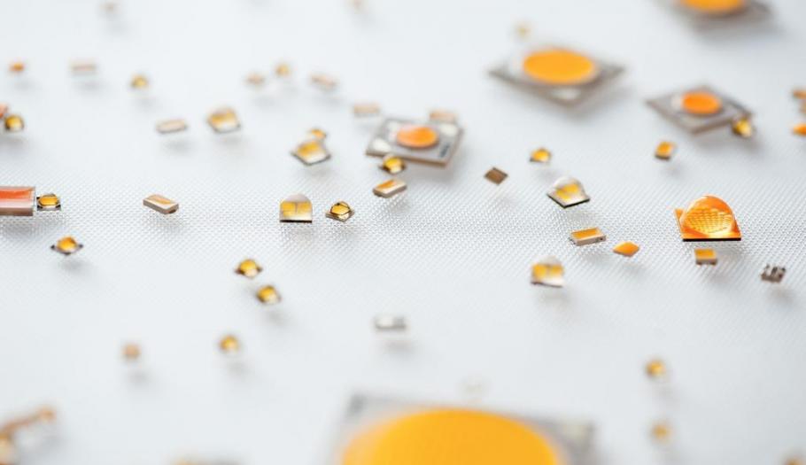
Obsolescence can be the stuff of nightmares for OEMs and will have an effect on numerous business functions. Purchasing and sourcing teams will need to establish possible new suppliers and stock of the end of life (EOL) parts, engineering teams will need to qualify alternate or substitute parts or even start again with a re-design. This is time-consuming and costly before even thinking about the retesting and recertifying that may be involved. Further consideration has to be production and manufacturing. Will the replacement component be suitable with current production methods, will there need to be a change? No wonder it causes such disruption to businesses.
Custom designed solutions could combat some of the issues caused by obsolescence. A purposeful design rather than “making do” can negate the need for additional components, components that could be high cost and high risk in terms of supply. A component that is hard to source, and rare, the likelihood of it becoming obsolete is high. So where does this leave you? If your product's functionality is reliant on that component you could have big problems – and expensive ones at that. As mentioned, re-design is a huge expense as is sourcing end of life components through specialist distribution. If you take control at the initial design stage you can mitigate the need for additional, unnecessary components, streamlining your supply chain and your production process. In addition, you’re also lessening the impact that obsolete components could have.
In terms of a custom LED solution, it is possible to achieve the lighting output, the efficacy and the exact size you need all manufactured and designed with the product life cycle in mind. LEDs will never be immune from obsolescence – this isn’t a bad thing though as it is usually for reasons of developed technology and even greater performance. Working with a strategic manufacturing partner who specialises in custom means this doesn’t have to worry you. Handling a change such as a next-generation LED can be done directly with limited impact on your supply. If the LED has the same footprint a redesign may not even be necessary, even if it is it’ll be worked out for you. The re-design will include predicted performance data, layouts that have a limited effect on Light Output Ratio (LOR) and testing in your own housing so you can generate new product data sheets quickly and efficiently. At the initial design stages, it is even possible to dual footprint keeping your options open to easily accommodate for alternative LED packages and give your product greater flexibility. You can effectively market 2 great products to suit your customer needs – high end and basic for example – with 1 PCB design. What’s more, it’s likely to cost less than you might think.
By considering custom as a solution you’re effectively managing obsolescence and determining a products life cycle yourself without being dependant on numerous suppliers. Not only this but you have a purpose-built solution matching your requirements precisely at little to no added cost, you’ll be working with a strategic partner who understands your product as well as you do and manages the product life through to next generation. In addition to saving costs from the impact of obsolescence, you’ll save with a reduction in material costs, engineering costs and lower inventory. What’s more, you’ll have simplified supplier relationships with better results, service and support from those relationships. All that and you’ll have your own brand and company image on the product – the product that is now completely differentiated putting you way ahead of the competition.
So, even if you simply want to develop a relationship with a manufacturing partner just to copy the previous part that has now been made obsolete or to totally negate the need to rely on standardisation and handle product design yourself, with a custom or even semi-custom solution you’re taking control of obsolescence and managing it.
The latest topic of conversation from Forge - Custom Optics. Give our brochure a read now to find out more.
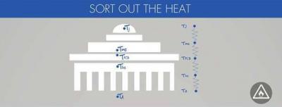
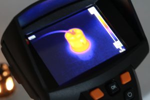
Where is the heat coming from?
Whilst LEDs are highly efficient, there is still an amount of electrical power that is converted to heat, not just light. LED overheating can be caused by many rather obvious design factors such as inadequate heat sinking and excess LED power. But a well-designed LED luminaire can be equally overheated by installing it in an environment for which it was not designed. To get the very best performance from the LEDs the excess heat needs to be conducted away from the LEDs – to avoid exceeding the recommended maximum operating temperatures. With as much as a 10% decrease in light output being attributed to temperature increases, getting your thermals in check when designing your LED solution is a must.
Effective thermal management is fundamental to the design process of an LED solution. We need to understand the application – any space limitations, the environment of the installation and power requirements can have an impact on heat dissipation. We also need to understand the performance, cost and efficiency targets to allow for an effective design that achieves an LED solution, that does what you want it to.
What damage can heat cause?
LEDs that overheat will degrade more rapidly in terms of:
In extreme cases overheating LEDs can result in physical damage to the LEDs themselves, plastic lenses, wires, connectors, printed circuit boards, drive electronics etc.
How to get your thermals sorted
Thermal design is intrinsic to every element of design including LED selection, PCB design and layout, and electronics design. When choosing the LED; the power, LED junction temperature and thermal resistance are all considered and compared.
The design and layout of the PCB is another way to conduct heat away from the LED. PCB materials have varying thermal characteristics, enlarged solder pads and thicker copper layers help to distribute the heat across the PCB. The addition of thermal vias – drilling holes and copper plating them - can also improve the thermal resistance of FR4.
Design with thermal simulations
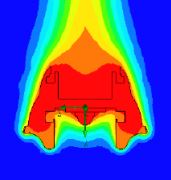
A heatsink transfers the generated heat from the LED board to the ambient air using convection and radiation. When we design heatsinks our aim is to optimize airflow and improve the thermal efficiency of the complete LED solution.
Using the latest in Computational Fluid Dynamics (CFD) Software we can easily simulate and analyse various heatsink designs to optimise thermal efficiency. With the ability to visualise airflow, calculate thermal resistance and model the application environment our engineers can very quickly evaluate designs, and even make tweaks to improve the thermal efficiency before moving into prototyping. This allows us to very quickly get to prototyping and production with a solution that works – we’ll also test to ensure that the solution runs to our simulations and predictions.
Download our Sort your Thermals leaflet now.
A one size fits all approach is rarely the best solution, and when it comes to lighting for horticulture, agriculture, and vertical farming that is definitely the case.
Whilst LED grow lights have been available on the market for over 10 years there is still a great deal of research being undertaken on how to capitalise on the benefits of LED and harness the potential of the technology for use with different plant species.
With LEDs, it is possible to create luminaires that have a fixed wavelength output, whether that is white full-spectrum LEDs or a prescribed mix of monochromatic LEDs, or indeed create grow lights that can be adjusted to provide varying wavelength compositions over the various phases of a plant’s development from seedling through to flowing or cultivation.
The directionality of LEDs also makes them ideal for use with optical systems to put light exactly where you need it in your growing environment. Indeed, with the use of bespoke optics, it is possible to have a common light engine that can be used in a top-lighting situation with one optic configuration and then an inter-lighting situation with a different optical moulding.
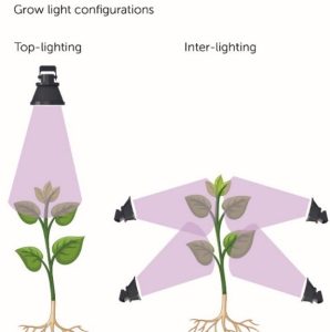
Fig.1 Grow light configurations, bespoke optics can be used in either configuration.
So how can we help?
Our expertise and capabilities can help you develop and manufacture an optimal solution to meet your requirements; we can help with everything from LED selection and circuit layout through to optic design and heatsink specification.
There is a wide range of LED types available that deliver high PPF/W (Photosynthetic Photon flux per Watt), from cost-effective white mid-power LEDs for full-spectrum lighting through to high-power monochromatic LEDs emitting blue 450nm, photo red 660nm and far-red 730nm.
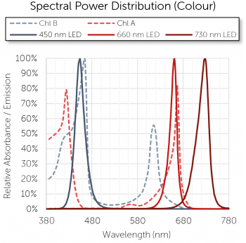
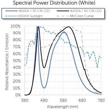
Fig.2 Spectral Power Distribution graphs
We work in conjunction with OEMs to determine the best wavelength requirements for a particular plant growth application, it is possible to utilise in-house photometry facilities to quantify PPFD (Photosynthetic Photon flux density) and the weighted YPFD (yield photon flux density).
The availability of in-house photometry is invaluable as it not only enables the analysis of the spectral output of the luminaire but also generate irradiance modelling to understand the distribution of the light over the plants around the fixture. If the output of standard lenses isn’t appropriate or indeed if you want to create a truly unique product from the outset then it’s possible to undertake the development of a custom optic to tailor the light to suit your needs.
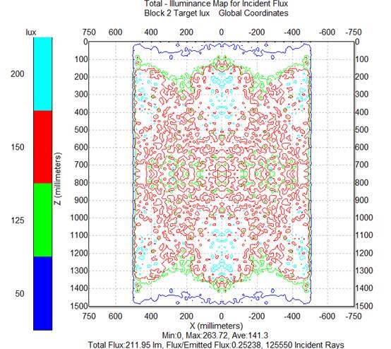
Fig.3 Irradiance map of distributed light
The process of delivering a custom optic involves a multidisciplinary approach of design, modelling, prototyping, verification and ultimately tooling for volume manufacture. There are various material choices that can be made from polymers through to glass, and the function of the lens as an integral component of the luminaire means that IP sealing and impact resistance (IK) can be considered as part of its design. The process of incorporating a custom optic also negates the need for additional reflectors which can often be necessary for secondary optics that are designed for general lighting, not grow lighting.
So if you’re an OEM specialising in plant growth luminaires and would like to explore further the potential to develop a new product with Forge get in touch now.
See some of our previous work in horticulture.
We are Forge – we’re passionate, inventive and charming. Offering fantastic career prospects in a great place to work and live.
Watch our very latest videos now.
Our IPC qualified engineers use the latest CAD software to design circuit boards that are optimised to be manufactured. The PCB design process combines component placement, tracking, material selection and thermal management to achieve electrical connectivity on a manufactured circuit board.
As tempting as it may be to just throw LEDs and other components on to the board, it is the process of clever component placement that keeps costs down, manufacturing easy (or as simple as possible) and quality high. We always design for optimal: manufacturability, thermal and optical performance - and good placement is the foundation of this. The arrangement of parts can impact reliability, assembly processes, solder joint integrity and testing. Many aspects of LED PCB design are unique to LEDs and generally unknown to the wider electronics industry. LED PCBs need to be designed to constrain LED movement during reflow soldering and track flood-fill needs to be optimised for thermal performance and capacitive coupling for example.
In addition to LEDs, we’re placing connectors, active and passive components, thermistors and more onto LED PCBs whilst considering mounting holes, through vias and optic placement. With so many considerations it’s no wonder PCB design is like solving a puzzle.
We haven’t even mentioned PCB physical size constraints and creepage and clearance tolerances that impact on placement, electrical test requirements (accessibility) and assembly limitations. Suitable clearance between components is required to avoid an over-voltage event on the board. Creepage is the shortest distance between components measured along the surface of the insulation material – clearance, on the other hand, is the distance between components measured through air. The more components there are to place the more difficult it can be to achieve creepage and clearance. Our team consider the material of the PCB, insulation and pollution that could occur when the PCB is in the application, they then apply the relevant tolerances for creepage and clearance for long-lasting performance.
![]()
Fig.1 – Creepage and clearance measurement
The PCB serves a number of purposes in LED-based circuit designs; most notably it provides the electrical connections between individual components and the electrical insulation of conductors from one another, but often the PCB also forms one of the very first elements of the thermal pathway between the LED component and the ambient air, whilst the PCB can also form a foundation onto which non-electronic components are also mounted I.e. lens and reflectors.
There are various PCB materials that can be used for LED applications: both FR4 and insulated metal substrate (IMS) are popular choices. Each material has its own relative merits, ranging from cost through to thermal performance.
IMS as a PCB material is comprised of three main elements; a metal base layer, a dielectric film, and a copper top-layer. The metal base layer forms the bulk of the PCB thickness and gives mechanical structure and thermal mass, typically the metal used will be aluminium as it offers good thermal performance versus cost. Not all IMS PCBs are the same, high-performance IMS materials have dielectrics with higher thermal conductivity, which ultimately can yield to a product with significantly longer lifetime.
In summary, IMS PCBs are inherently very good at dissipating heat because they are made almost entirely of metal; however, they are typically more costly than FR4 material
FR4 is what most people think of when you say, ‘PCB material’. It is used widely in all manner of electronics and so it is a very familiar material for designers of circuits. FR4 material is constructed from reinforced resin onto which a copper foil has been mounted. As the resin material is an insulator it is possible to create a laminate of many circuit layers placed one on top of another, interconnected as required. Given the thermal performance of IMS surely FR4 is inferior? Not necessarily. With clever PCB design, it is possible to achieve good thermal conductivity through FR4 materials, essentially creating thermal pathways through the resin that do not impact the electrical functionality of the PCB.
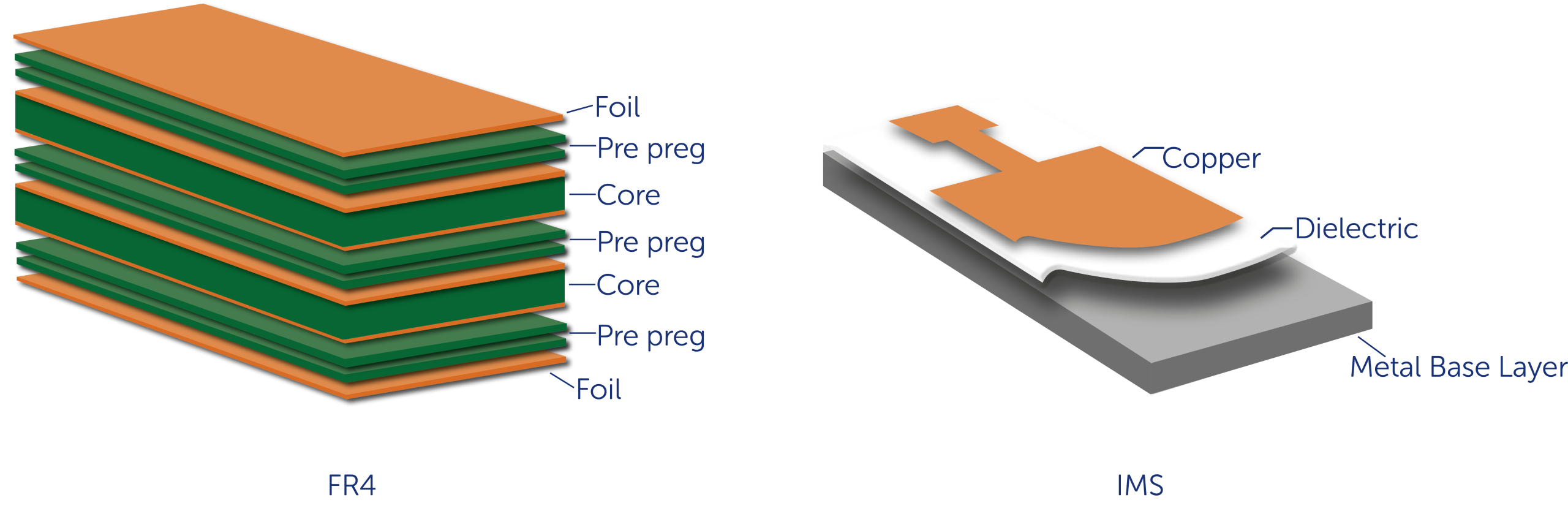
Fig.2 – PCB composition of FR4 and IMS
Materials are selected to provide structural strength to support the electronic components and to dissipate the heat from the conductors and the components. Excessive heat is the enemy of the PCB and must be managed for reliability and proper function. Our designers look to maximise heat dissipation with the use of thermal vias, smart component placement and PCB material choice.
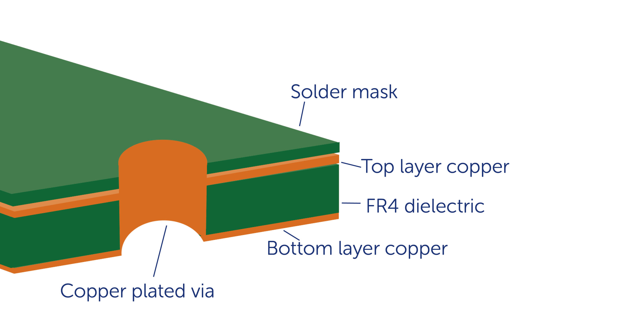
Fig.3 – Cross-section of thermal via in FR4 substrate
Heat exchange is not efficient with just the ambient air around a hot device. However, heat can be transferred away from the critical electrical components with the use of thermal vias. Heat is transferred to a thermal via by conduction and this allows heat to move away from the components.
Adding vias will improve the thermal resistance of an FR4 board, provided they are placed appropriately, and the board thickness has been considered to determine the hole diameter. Thicker boards with very small holes are more difficult to manufacture – and more expensive. An acceptable aspect ratio is ≤6:1. Increasing the plating thickness during PCB production improves thermal resistance.
Component placement for even heat distribution, LED heatsinks and the application of the final LED PCB are all considerations throughout the PCB design to ensure effective thermal management and reliability.
Once the components are placed the tracking can begin. The task of tracking is to create geometries such that all terminals assigned to the same net are efficiently connected, no terminals assigned to different nets are connected, and all design rules are obeyed. Through careful tracking, we’re looking to avoid opens, crosstalk and shorts whilst ensuring good quality manufacturing and reliability. At this stage, our designers are thinking track width, symmetry, space and mounting holes.
An adequate track width ensures the desired amount of current is transported throughout the board without overheating. The estimated current and copper thickness along with ambient temperature, track length and track spacing determines the optimum track width.
Not all tracks will be created to equal widths. Power and ground tracks will have much more current flowing through them, making these much wider than the average tracks means there won’t be excess heat flowing through thinner tracks and damaging the board.
As we’ve already mentioned – our circuit boards are optimised for manufacturing. This is why our designers leave enough room between all tracks and pads and radius corners. If using 90 degree angles with tracks there is a higher probability the etched track being narrower than the required track width. Incorporating chamfered or a radius corner avoids this possibility.
A multi-layer PCB is a PCB that has more than 2 layers, they are ideal when space is tight – rather than increasing physical dimensions alternating layers of copper with insulating material can be added between to save on space, improve assembly and increase the area available for tracking.
There are two essential functions of protective coatings/surface finishes applied to the PCB – protect the exposed copper and provide a solderable surface for assembly. After the finish, there is also legend which allows for required markings that can assist with manufacturing and field installation. This also allows us to incorporate your logo into the PCBA for great brand awareness. The most commonly used surface finishes are:
HASL (Hot Air Solder Levelling), OSP (Organic Solderability Preservative), immersion tin, electrolytic nickel/electroplated gold, immersion/silver, ENIG, ENEPIG. Each surface finish has pros and cons and our designers will specify the most suitable finish prior to manufacturing. In most cases, OSP is used as it gives a flat surface required for fine pitch components and the application process is simple.
Smart PCB design is fundamental to manufacturing your ideal LED solution. With clever design, we’re able to incorporate double-sided FR4 PCBs, and multilayer PCBs for optimum performance when space is tight. At the heart of all our PCB designs are your requirements and application. For more information on our expertise or to get your hands on your very own LED solution designed and manufactured by us contact us today.
Whatever the horticulture application, we’ll manufacture your ideal LED lighting solution. Download info on our capabilities now.
The possibilities are endless with the most efficient, cost-effective light source available. Download our leaflet to find out more now.
High quality LED PCBAs on time and to your budget. Download our leaflet to find out more now.
Effective LED thermal management is fundamental to reliable LED solutions. Forge has the expertise you need. Find out more now.
Get on board with on-board electronics with Forge. Find out more now.
Find out more about Forge now.
‘Traditional’ monochrome Amber LEDs are made solely from compound semiconductors such as AlInGaP and emit a very narrow colour spectrum from the bare LED chip itself. White LEDs comprise a blue-emitting LED chip covered with phosphors which convert some blue light to green/yellow/red which in combination with the blue creates full-spectrum ‘white’ light. PC-Amber LEDs comprise a blue-emitting LED chip but with phosphors (PC) tuned to maximally convert (PC) the blue light to a broad colour spectrum amber, the blue light is mostly filtered out.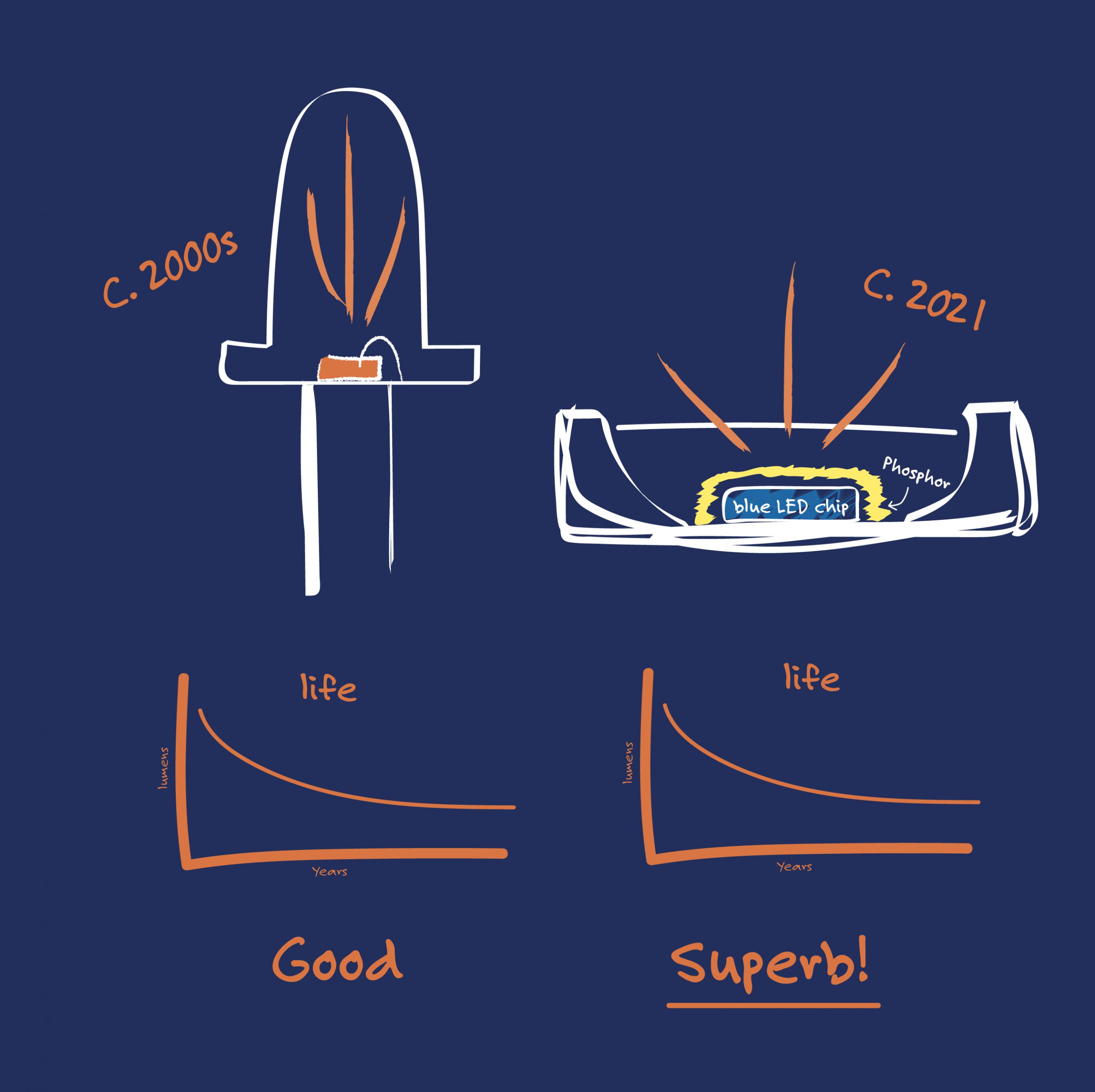
Results summary: L70 lifetime projection (informal):
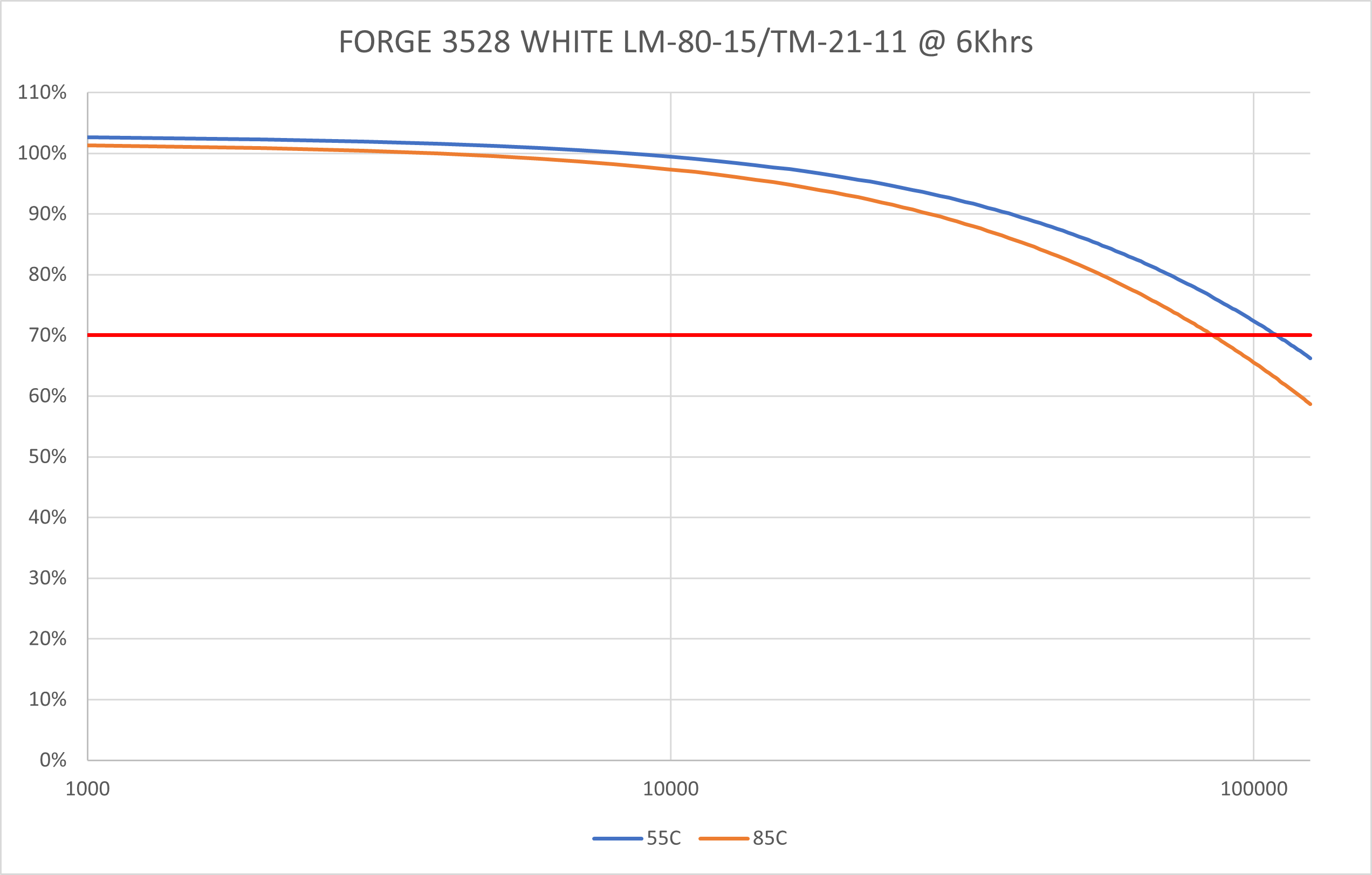
Forge 3528 White@20mA: 55°: 110Khrs, 85°: 85Khrs ✔
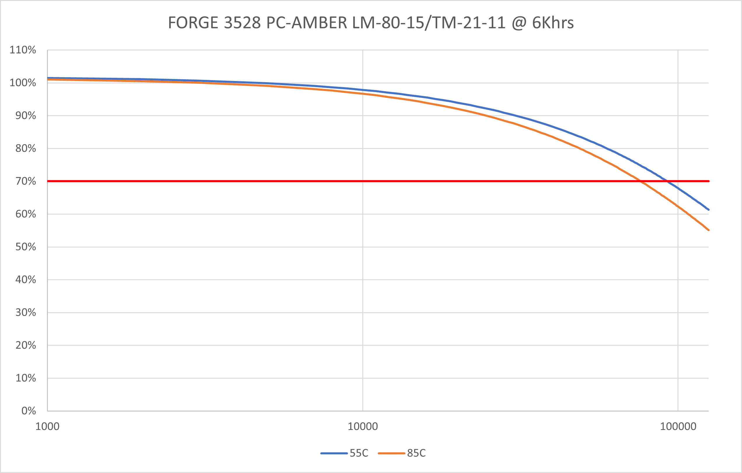
Forge 3528 PC-Amber@20mA: 55°: 93Khrs, 85°: 77Khrs ✔
Colour LEDs provide unparalleled design flexibility, allowing architects and engineers to create unique and visually stunning lighting designs. From accent to general lighting, colour LED technology and custom colour-mixing optics are revolutionising LED solutions like never before. If you think you don't have a need for colour, think again.
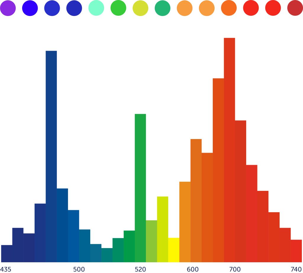
Colour LED technology is revolutionising various industries, including horticulture, agriculture, healthcare, entertainment, and poultry farming.
Healthcare utilises high-intensity blue and red LED lights (400-500 nm and 600-700 nm) in phototherapy lamps for skin treatment and sleep disorder therapy.
Agriculture and poultry farming apply blue and red LED lights (450-460 nm and 630-660 nm) to control photoperiod and improve plant and poultry growth.
Horticulture benefits from blue, red, and far-red LED lights (400-500 nm, 600-700 nm, and 700-800 nm) to enhance plant growth and increase yields.
Access to our global LED portfolio, including Lumileds, a leading producer of colour LEDs, combined with our custom LED design and manufacturing capabilities, can meet all your needs.
RGB LED technology is a key element of designing with colour. Consisting of three separate LED chips, RGB LEDs emit light in the red, green, and blue spectrum which can be combined to produce a wide range of colours. The brightness of each RGB LED chip can be controlled independently, allowing precise control over the colour and intensity of the light produced. This control can be achieved through the use of pulse width modulation (PWM) or digital-to-analogue converters (DACs).
To achieve accurate and consistent colour representation, RGBW LEDs include a white LED chip. Lighting applications such as architectural, industrial, stage, outdoor, and even automotive benefit from RGBW LEDs' increased brightness and enhanced energy efficiency.
For industrial/workplace applications, improved colour rendering offers the following benefits:
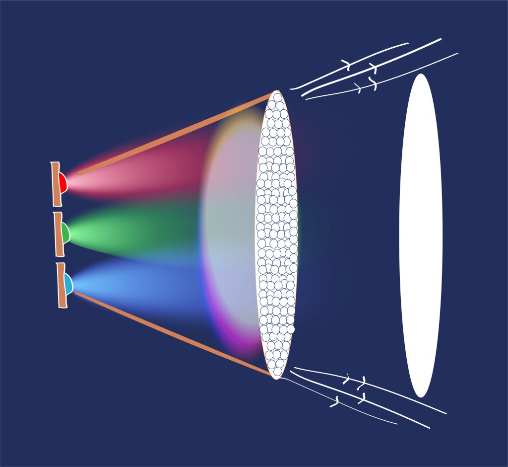
For even more design flexibility, colour LED solutions can be combined with colour-mixing optics to produce a wide range of colours. Using diffraction gratings, mirrors, and lenses, these optics blend different LED chips and produce specific colour temperatures and hues.
LED lighting systems, whether RGBW or standard colour, require control to adjust the colour and intensity. This can be accomplished using LED drivers or controllers, smartphone apps, remote controls, or voice assistants. Depending on the application, these systems can be controlled using DMX, DALI, or 0-10V protocols. We can integrate Ethernet, Wi-Fi, and DALI control interfaces based on your requirements.
The advancement of colour LED technology continues to provide a versatile option for lighting design and innovation. With cutting-edge solutions, leading companies like Lumileds are driving the industry forward. The future of custom LED lighting solutions is bright.
We have the capability, expertise, and global LED portfolio to help you develop the ideal custom LED solution for your needs. Talk to us about your requirements today, and you will walk away with your ideal custom LED solution.
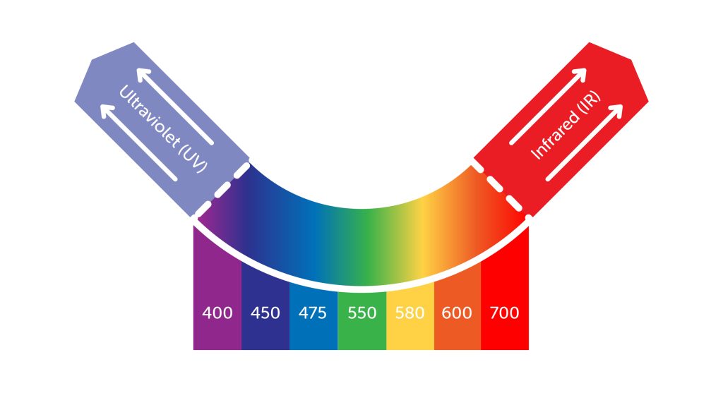
Infrared and Ultraviolet are the terms used to describe radiant light that is beyond the limits of human vision at the extreme ends of the colour spectrum.
But just because we humans are not able to perceive these ‘invisible’ colours does not mean that they are not of use to us! And consequently, there’s a huge range of LED solutions available nowadays that can generate Infrared and Ultraviolet light.
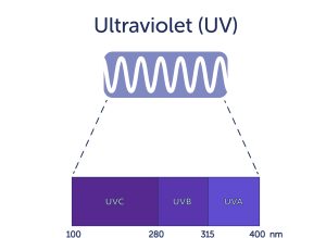
Ultraviolet light is generally subdivided into 3 categories- UV-A, UV-B & UV-C. LEDs are available that operate in all 3.

UV-A is very familiar to us as the component of sunlight that generally causes skin ageing (suntan). LEDs that generate UV-A find widespread use in areas such as the curing of glues & inks and inspection illumination. UV curing ranges from professional industrial adhesives to cosmetic nail varnishes. UV inspection is widely used industrially and for example in banknote verification.
UV-B is familiar to us as the component of sunlight that causes skin damage (sunburn). LEDs that generate UV-B under controlled conditions can be used to treat skin conditions.

UV-C is entirely filtered out by the ozone layer so does not occur naturally on Earth. Consequently, artificially produced UV-C light is extremely damaging to DNA and hence it finds uses in germicidal sterilisation. UV-C LEDs are now becoming quite widely available for this purpose.
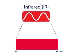

Infrared radiation ranges from near-visible deep red to invisible radiated heat but LEDs are only able to operate effectively toward the near-visible range of the spectrum. IR LEDs have been used for many decades as the communications source in remote controls for appliances such as TVs. And they may be used to illuminate low-light scenery in night vision applications or to resolve challenging detail in machine vision systems. Other applications include light therapy, industrial sensors, and scientific instrumentation.
We will combine our technical expertise, engineering experience, and ability to source LEDs from an unrestricted global portfolio to deliver an LED solution that meets all your needs.
So if you're thinking of broadening your spectrum and exploring the possibilities of UV and IR then speak to us.
The health benefits of quality LED lighting include balanced circadian rhythm, reduced headaches and increased productivity and performance in the workplace. These benefits are now well documented, with more and more LED manufacturers releasing LEDs developed for the human-centric lighting market.

The benefits beyond human well-being are also well documented. Research suggests the quantity and quality of light can affect the milk yield and fertility of cattle, poultry produce higher quality eggs at a greater rate with the right light and plant growth can increase up to 40% with a controlled LED environment producing more fruit and vegetables.
With these kinds of applications, the living environment is a fundamental consideration and with the use of using the LED technology, it can be enhanced considerably.
So, you're wondering how you do that? Simple, speak to us. With Forge as your LED manufacturing partner, we'll choose the right LED, design an optic that focuses the light where it's needed and we'll manufacture it all for you.
As an added value manufacturing partner Forge have the capabilities to tailor the manufacturing process to your needs.
Do you currently have Chinese manufacturing partners in your supply chain? Our Intra China manufacturing network is a unique trading model that is designed to make your life simpler. We'll coordinate from Forge UK so you can manufacture and trade locally in China with ease.
It's that simple. We'll take your Forge UK designed, developed and tested product through to manufacturing with our Intra China trading process. Did we mention the whole process is supported by our 28 years of knowledge and experience? With ISO:9001 quality assured measures throughout and a dedicated UK account manager. We can reduce your planning and purchasing challenges and improve your business efficiencies.
To take advantage of our Intra China process simply call us today.